 HuiTong
  2025-06-13
Stick structure
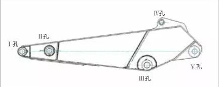
The bucket rod of the excavator is welded by steel plates. Generally, there are 5 shaft holes on the bucket rod, namely, bucket shaft hole (I hole), connecting rod shaft hole (II hole), boom shaft hole (III hole), shovel Bucket cylinder shaft hole (IV hole) and stick cylinder shaft hole (V hole), each shaft hole is inlaid with a bushing

Causes of shaft hole wear
When the excavator is working, the bucket is subjected to an impact load, which first acts on the I hole on the stick. The transmission path of I hole bearing impact load is: bucket→pin shaft→sleeve→inner wall of I hole.
Since the hardness of the shaft sleeve is greater than that of the I hole, the impact load can cause plastic deformation of the inner wall of the I hole, resulting in the destruction of the interference fit between the inner wall of the I hole and the outer diameter of the shaft sleeve. When the friction between the pin and the shaft sleeve is greater than the friction between the shaft sleeve and the mating surface of the I hole, the shaft sleeve will rotate along the inner wall of the I hole. After the shaft sleeve rotates, the hole I will be severely worn, which will cause the bucket to shake during operation and affect the efficiency of the excavator.
Axle hole wear repair process
(1) Choose repair technology
We take the wear of the stick I hole as an example to describe its repair process. After the mating surface of the I hole and the shaft sleeve is severely worn, the I hole needs to be repaired. The surface repair techniques of metal parts include electroplating, electric brush plating, thermal spraying, surfacing, laser cladding, surface adhesion, etc., and the thickness and strength of the coating repair. Taking into account the wear of the I hole, the convenience and economy of the above-mentioned repair technology, the thickness and strength of the cladding repair, we chose gas shielded welding and manual arc welding surfacing repair technology.
(2) Surfacing shaft hole
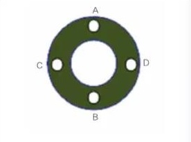
Divide the I hole into 3 equal parts according to the aperture direction, and ensure that the welding area is in the horizontal upward position by hoisting or flipping, where the A area is the horizontal welding position and the B area is the horizontal welding position. Welding area parameters. In addition, for heavy scratches, wear surfaces, and side wear surfaces), different parameters are used to weld, and the surfacing thickness depends on the degree of wear of the I hole.
During the welding process, the welding wire is welded from the outside to the inside along the direction of the shaft hole. In order to prevent unfusion defects, the last weld should be pressed at 1/2~2/3 of the first weld during welding. The thickness of each layer is controlled at 2~3mm, and slag removal is required between the welding layers. After the surfacing is over, the aperture size is about 10% smaller than the standard aperture to facilitate machining. The grease hole on the inner wall of the shaft hole is directly surfacing welded. After the shaft hole is machined, it can be drilled manually with a drill.
Hoist the stick to the flat welding position of the shaft sleeve end face, and surfacing the shaft hole end face. Before surfacing, grind the arc starting end of the weld, and use the girth welding method to weld from inside to outside. After surfacing welding, both ends of the shaft hole are 5~7mm thicker than the standard size to ensure the required size for machining. During the welding process, the welding seam should ensure a smooth transition, and no sagging, pores and obvious gullies are allowed to avoid affecting the machining accuracy.

(3) Machining shaft hole
After the I hole diameter and end face surfacing are completed, it needs to be machined. The machining steps are as follows.
First, hoist the stick and pre-assemble it. Hoist the surfacing stick with I hole to the machining center platform for pre-installation. At this time, first use a steel ruler to adjust the symmetry of hole II, hole III, V hole and the reference plane of the machining center to make the symmetry deviation within 1mm to ensure the accuracy of subsequent machining adjustment.
Secondly, make precise adjustments to the stick and complete positioning. Use the ruby probe of the machining center to accurately adjust the stick. Use the ruby probe to measure the size of the II and III holes and adjust the stick. In order to determine the size of the center coordinates of hole II and hole III, move the ruby probe up, down, left, and right the same distance to points A, B, C, and D. These 4 points are close to the outer edge of hole II and hole III. The points should be smooth and free of wear marks.

Once again, determine the I-hole machining coordinates. Set the Z coordinate axes at these 4 points on the hole end face as A, B, C, D, set the stick II hole end face coordinates as A1, B1, C1, D1, and the III hole end face coordinates as A2, B2, C2, D2 ; Adjust the stick to ensure that the error of each coordinate point is less than 0.1mm. Measure the center coordinates of hole II, hole III, hole IV, and hole V, and determine the machining coordinates of hole I through MDS software and machine tool program.
Finally, the I hole is processed according to the technical requirements of the drawings. If there are pores in the repair welding hole after processing, it should be properly repaired according to the pore condition. After passing the inspection, the I hole of the stick will be repaired.